Enhanced LACP Support on a vSphere Distributed Switch
Article ID: 315280
Updated On:
Products
Issue/Introduction
Resolution
- To configure Enhanced LACP with vSphere Distributed Switches in vSphere, you must use the vSphere Web Client.
- For more information on configuring Multiple Link Aggregation Groups (LAGs) with the vSphere Web Client, see the LACP Support on a vSphere Distributed Switch section of the vSphere Networking.
Enhanced LACP support allows you to connect ESXi hosts to physical switches that use dynamic link aggregation. Multiple Link Aggregation Groups (LAGs) can now be created on a single Distributed Switch to aggregate the available bandwidth of physical NICs connecting to LACP port channels. In vSphere 5.5 and beyond, up to 64 LAGs can be created per vSphere Distributed Switch.
Enhanced LACP support on a vSphere Distributed Switch
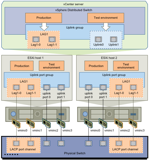
Each LAG can be configured for either Active or Passive LACP modes. In an Active LACP LAG, all ports are in an active negotiating state. The LAG ports initiate negotiations with the LACP port channel on the physical switch by sending LACP packets. In Passive mode, the ports respond to LACPDUs they receive but do not initiate the LACP negotiation.
Note:
- If the physical switch is configured for active negotiating mode, it can be left in Passive Mode.
- If LACP needs to be enabled and Active mode is unavailable, it is highly possible that the Physical Switch is not configured for LACP.
- The Physical switch might be configured with EtherChannel or Port Aggregation Protocol.
- Consult with your Physical Switch vendor or Network Administrator for more details.
For more information, see Enabling and Disabling LACP on an Uplink Port Group using the vSphere Web Client (2034277).
vSphere LACP supports these load balancing types:
- Destination IP address
- Destination IP address and TCP/UDP port
- Destination IP address and VLAN
- Destination IP address, TCP/UDP port and VLAN
- Destination MAC address
- Destination TCP/UDP port
- Source IP address
- Source IP address and TCP/UDP port
- Source IP address and VLAN
- Source IP address, TCP/UDP port and VLAN
- Source MAC address
- Source TCP/UDP port
- Source and destination IP address
- Source and destination IP address and TCP/UDP port
- Source and destination IP address and VLAN
- Source and destination IP address, TCP/UDP port and VLAN
- Source and destination MAC address
- Source and destination TCP/UDP port
- Source port ID
- VLAN
Note: These policies are configured for LAG. The LAG load balancing policies always override any individual Distributed Port group if it uses the LAG with exception of LBT and netIOC as they will override LACP policy, if configured.
These two configurations are going to load balance based on the traffic load which is better than LACP level load balancing.
Additional Information
Converting to Enhanced LACP Support on a vSphere Distributed Switch- "Source vCenter Server has instance(s) of Distributed Virtual Switch at unsupported lacpApiVersion"
Limitations of LACP in VMware vSphere
Cannot convert to the Enhanced LACP support
Host requirements for link aggregation (etherchannel, port channel, or LACP) in ESXi
Configure Virtual Switch with an EtherChannel (or port channel)
Feedback
