Deploy a Silicom STS NIC device
Article ID: 303604
Updated On:
Products
Issue/Introduction
VMware Telco Cloud Automation(TCA) expedites onboarding of worker node with Silicom STS NICs (STS4 and STS2) for LLS-C1 and LLS-C3 deployments.
The support for Silicom STS has been integrated into VMware Telco Cloud Automation (TCA) for simplifying workload deployments. Silicom timing pod is created and run in a workload cluster managed by VMware Tanzu Kubernetes Grid that is integrated into VMware Telco Cloud Automation. Onboarding of the Silicom device is done through the Kubernetes operator framework in VMware Telco Cloud Automation.
The system clock is synchronized to the high accuracy timing provided by the STS timing pod. DU workloads that run within the VM derive
their timing from the VM.
The timing Pod distributes time to connected RUs using a virtual function (VF) from each physical function (PF).
LLS-C1 Deployment with STS card
Environment
2.3, 3.x
Resolution
Prerequisites / Recommended Version
The following firmware and driver versions (or higher) are recommended
for use with STS cards.
| Firmware version | 4.01 0x80014757 1.3256.0 |
| ESXi Driver | Icen 1.9.5 |
| ice (PCI passthru) | 1.9.11 |
| Iavf | 4.5.3 |
| tsyncd | 2.1.2.11 |
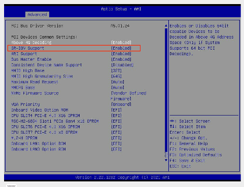
Enable SRIOV in BIOS Settings
BIOS -> Advanced -> PCIe/PCI/PnP Configuration -> SR-IOV Support -> Enabled
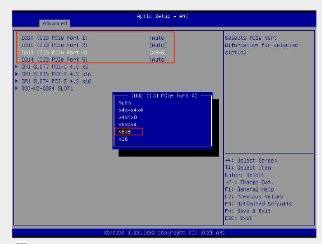
Port Bifurcation
STS2 has 8 x 10G ports. Port bifurcation is not required to see all the ports.
The STS4 card needs to be inserted into one of the PCI slots supporting x8x8 bifurcation.
BIOS -> Advanced → Chipset Configuration → North Bridge → IIO Configuration → CPU Configuration
As per the below screenshot, PCI slots 1, 2, 4, 5 supports port bifurcation. STS4 card should be inserted in one of these slots and x8x8 selected.
Summary of steps to enable STS cards through TCA:
- Prepare and deploy Host Profile
- Create a nodepool on ESXi host with STS
- Onboard a CSAR and add details for STS PF/VF and USB devices
- Instantiate Network Function using the CSAR
- On workload cluster, deploy the tsyncd daemonSet using helm.
Enable STS cards through TCA:
- Prepare and apply the STS Host Profile to enable passthrough on PF0 and SRIOV on other PFs.
- Log into TCA Manager and navigate to Infrastructure > Infrastructure Automation.
- Create a new Host Profile and configure the Physical Function (PF) drivers to have Passthrough enabled on PF0 and SRIOV enabled on the other PFs (1-3).
- Refer to the Host Profile example below to enable PCI passthrough on PF0 and SRIOV on other PFs (1-3).
- Use the attached sts2-ptp-vf Host Profile to create a new Cell Site Group named sts2-ptp-vf.
- Attach the ESXi Host with the STS card to the new sts2-ptp-vf Cell Site Group.
- Create a node pool using the ESXi host with the STS card.
- Login to the workload cluster as the capv user and obtain the full name of the worker nodes associated to the new nodepool.
kubectl get nodes –A - Confirm the worker node VM is labeled with 'telco.vmware.com.node-restriction.kubernetes.io/sts-silicom=true' by running the following command:
kubectl get nodes newNodeName --show-labels
Note: Replace newNodeName with the node name from step 3. -
Log into the management cluster.
-
Validate the PF groups and their associated devices by reviewing the output of the esxinfoprofile and esxinfo commands.
-
List all the ESXi profiles by running the following command:
kubectl get esxinfoprofile -n tca-system -
Select the esxinfoprofile for the sts2-ptp-vf host profile by running the following command:
kubectl get esxinfoprofile -n tca-system sts2-ptp-vf-o yaml -
Run the following command to obtain all the ESXi information:
kubectl get esxinfo -A -
Run the following command to select the ESXInfo for the STS host by matching the ESXi Host FQDN from step 3:
kubectl get esxinfo -n tca-system <esxi-hostname> -o yaml
-
-
Attach the STS card’s PF/VF and USB devices.
-
Onboard a new CSAR with the following spec details added under the infra_requirements: section. See attached csar_additions file.
-
Add STS PF0 in PCI passthrough mode under the passthrough_devices: section.
-
Add the VF from other PFs as an SRIOV Network Adapter under the network:devices: section.
-
Add the USB devices under the usb_devices: section.
-
-
Remove the linuxptp, phc2sys and ptp4l settings from the CSAR. See attached csar_deletions file.
-
-
Instantiate the Silicom NF CSAR with the modifications detailed in the previous step.
-
Confirm the names of the STS devices match the names defined in the Silicom NF CSAR.
-
Log into the worker node VM.
-
Run the following command to confirm the STS device names match what is defined in the CSAR, e.g. sts-ethX:
ip a
-
- Download the Silicom Tsyncd helm charts and deploy the Tsyncd daemonSet onto the workload cluster.
-
Run the following command to add the helm repository:
helm repo add sts-charts https://silicom-td.github.io/STS_HelmCharts/ -
Run the following command to confirm the Silicom STS-charts are present:
helm search repo sts-charts -
Run the following command to download the sts-charts package:
helm pull sts-charts/sts-silicom
Note: You can ignore the following warnings:
WARNING: Kubernetes configuration file is group-readable. This is insecure. Location: /home/capv/.kube/config
WARNING: Kubernetes configuration file is world-readable. This is insecure.Location: /home/capv/.kube/config -
Un-tar the sts-charts package:
tar -xvzf sts-silicom-0.0.8.tgz
-
- Create a new yaml file to overwrite the default Tsyncd helm charts
- Run Tsyncd in Grand Master (GM) mode.
-
Download the attached gm.yaml file
-
Using the gm.yaml file, run the following command to install Tsyncd into the tca-system namespace:
helm install -f gm.yaml --debug sts-gm --namespace tca-system ./sts-silicom
-
Run the following command to confirm there are 4 pods, with the sts-gm prefix, in READY state:
kubectl get pods -n tca-system - Run the following command to confirm the sts-gm-cfg configmap has been created with the DATA value set to 2.
kubectl get configmap -n tca-system -
Run the following command to confirm the sts-gm-grp service has been created:
kubectl get services -n tca-system
Troubleshooting STS installation:
-
Use the following commands to review the Tsyncd logs messages and confirm Tsyncd has started without error:
kubectl logs -n tca-system sts-gm-tsy-<podname> -c sts-gm-tsy -f | grep –v APR_QIF_MSG_EVENT_AWAKE -
Check GNSS log messages using the following command:
$kubectl logs -n tca-system sts-gm-tsy-<podname> -c sts-gm-gps -
Check host time synchronization logs using the following command:
$kubectl logs -n sts-gm-tsy-<podname> -c sts-gm-phc
Note: Replace sts-gm-tsy-<podname> with actual sts-gm-tsy-<podname> value.
Attachments
Feedback
